Status>Connections color confusion

Hi
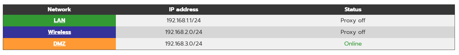
I recently installed IPfire on a new mini pc for my home setup with 4 NICs, and I went with the Red + Green setup initially, later I ran setup and change it to green, red, Orange Blue, although, nothing is plugged into Blue and Orange yet. I have a cable modem directly plugged in to RED and my ISP assigned me an IP via DHCP, my green is connected to a Switch and this one has all my PC’s and (my old router in AP mode), there are no other routers or anything else doing NAT. I intend later to connect my AP to BLUE once I understand IPFire better.
Everything WORKED, I been enabling features as I read the manual to get myself familiarized with each one and see how everything works, I even color coded the NIC’s and wrote down the MAC’s so I am sure I am connected to the correct interfaces, I can access all my devices on green, Wireless works, all devices can get to the internet fine.
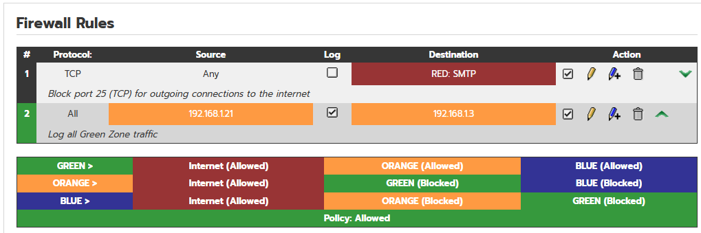
When my confusion is, when I go to Status > Connections, I don’t see any green connections, I was wondering if this is normal, because probably my lack of understanding of how masquerading works or something else, but I see all my private IP’s orange going to red. For instance, and pardon my ignorance :smiley:
Source “Private IP” port 50281 Dest. IP: “my IPfire router IP” port 444
orange to orange

or
Private IP > Public IP port 57536 Dest. IP: 74.125.170.106 port 443
orange to red

But shouldn’t this be Green to Green for the first example and Green to Red for the second?

also, when I connect to my devices and copy files between on the switch that is on green, shouldn’t I be looking at green to green under connections?

So I decided to do a test and make a simple firewall rule between 2 devices on green, I entered the IP on source and dest IP’s, all protocols, Accept, log rule and activate rule, then update, once back at the main Firewall rules page, I see my new rule created orange to orange, but those IP’s are green.

What am I doing wrong?
I am sure I am not connected to the orange NIC.

Every time I watched a video that shows the connections page, they are using private IP’s on their homelabs, and for them it shows in green > red, so I am confused as for why this is happening, and it was happening when I originally configure it with just Green + Red only.

Thanks

Firewall rule 2 is not going to work.
You can’t Firewall green to green traffic.
Your rule looks like it is part of the DMZ.
Your different zones all need different
IP ranges.
Like 192.168.1.0/24
192.168.4.0/24
192.168.6.0/24
Let us see your main page.

Status-> connections page should be called Status-> traffic as its the traffic that has transpired recently.

I actually edited the main page so I can see at a glance what ports was up an what speed they were running. But I do want to find a more refine way of doing it as well as trying to have the in/out traffic per net like the red has displayed on the top right of the gui. Maybe have all nets across the top with the red,

But your problems with networking comes from not configuring ipfire correctly.

each color zone is a separate ip network.
To beak down the default behaviour of this:
Green is configured so network clients with each other and have internet.
Blue is configured so the clients can connect to the internet and no one else.
Orange is configured so clients are statically assigned and connect to the internet and do not communicate with any other network.

This system uses separate networks so ip and netmask ensures routing isolation and better latency due to the efficient routing scheme. Other systems try to use vlan for this function but only somewhat isolates (because VLANS can be hacked in a network) and degrades the performance since it has to add and subtract a vlan tag out of each packet of information.

So you need to come up with internal numbering schemes for your networks that will be easy for you to identify. I just finished my build on my next machine, which has 6 10Gb ports for LAN and a 2.5G card for WAN. Which will be connected to a Doscis 3.1 cable modem. My blue network I use a router in access point mode and run a dhcp server internally.

Red - DHCP (port)
Green - 10.77.77.200 (port) DHCP range 10.77.77.1 - 10.77.100
Blue - 10.66.66.200 (port) DHCP range 10.66.66.1 - 10.6.66.100
Orange 10.69.69.200 (port)

So when I run setup I configure these primary ports. The other ethernet ports, I will assign them inside the web gui to bridge them to whatever color I need them. But I decided this time to make the other ports green and assigned them to that network by bridging them. My green computers directly connect to the ipfire router while my wifi and voip are going to be connected to a 10Gb to 4 port 1Gb switch and my NVR and printers will be connected by a different switch on the orange network, that I added the firewall rule to block all internet from it. Others use this network as a DMZ for their web hosting or other web servers, but I’m configuring orange as an internal device network.

So to fix your networking issue, you need to log in to the ipfire at the machine and run setup at the command prompt by typing setup and define the color interfaces and their ip addresses.

You are so right, my zones were all in the same range; I ran setup, change blue and orange to separate ones, checked connections, and now I see color as expected. I deleted the FW rule.
Before:


After

1 Like

Your BLUE and ORANGE IPs cannot be 192.168…x.0!
This is the network address of these zones.
Change to 192.168.2.1 and 192.168.3.1.

2 Likes

+1 to changing blue and orange. Because the ending number has to be greater than 0

Thanks for sharing, I love the idea of using the orange zone as an internal network by adding a simple rule as you described and keeping those devices on a separate Vlan.
I have learned a lot, I am glad to have discovered ipfire.
Thanks for you input.

2 Likes

The color is the whole device network. And within each color networks you can assign vlans on top of this. But STP has to be configured as its not configured by default and uses the Linux’s default stp scaling that does a good job as long as the hardware setup is simple.

1 Like

I believe you are refencing the network zone configurations, and I have left mine as “native”; I also went back to setup and changed the IP ranges to +1 and I am now seeing the colors properly and things make sense now.

1 Like

To clarify some terms ( based on private 192.168.x.y with 24 Bits identification ):

  • network ( in CIDR ) : 192.168.x.0/24, with x in { 0, …, 255 }
  • IP range: 192.168.x.0 … 192.168.x.255
  • broadcast address: 192.168.x.255
  • IPs for devices: 192.168.x.1 … 192.168.x.254

For easy comprehension select 192.168.x.1 for your IPFire.
Each network ( zone ) must be disjunct. Means with ( GREEN:192.168.x.0/24, BLUE:192.168.y.0/24, ORANGE:192.168.y.0/24 ) x≠y≠z must be true.

BTW: The ORANGE zone has a special meaning in IPFire, see www.ipfire.org - Step 5: Network Setup and www.ipfire.org - Firewall Default Policy

2 Likes