IPFire and Cisco equipment - A how-to guide

I wanted to share my experience with adding a Cisco 3750X and Cisco 5508 WLC to an IPFire setup.

Perhaps others more experienced than me, will chime in and educate us all on better ways to do this (hint hint)!

Let me preface that I am “greener than green” when it comes to VLAN! There was no specific business or technical driver behind this exercise. I wanted to learn more about the art of possible.

Let me start with the environment:

  1. IPFIre 2.25-144
  2. Red (DHCP), Green (192.168.111.x) and Blue (192.168.112.x)
  3. Cisco 3570X 48 POE ports with 2 GLC-T 1000BASE-T SFP Transceiver
  4. Cisco 5508 WLC with 2 GLC-T 1000BASE-T SFP Transceiver
  5. 3x Cisco 3702i and 1x Cisco 3602e with Cisco AIR-RM3000AC

The ultimate goal was to connect 2 of the 3702 and the 3602 (one in the basement, one on the main floor and the 3602 in the attic) to the Green network and the remaining 3702 to Blue.

As an FYI to those interested, I purchased the used Cisco equipment on ebay for about $400US.

After watching several youtube videos, I learned more about the concept of VLAN tagging and Trunk. I found this video (and the associated series) to be extremely informative.

  1. IPFire uses a Default VLAN (I am still a little fuzzy on this)
  2. Cisco switches use the Default VLAN (which defaults to VLAN 1)
  3. Untagged VLAN

==== Implementation Steps =====

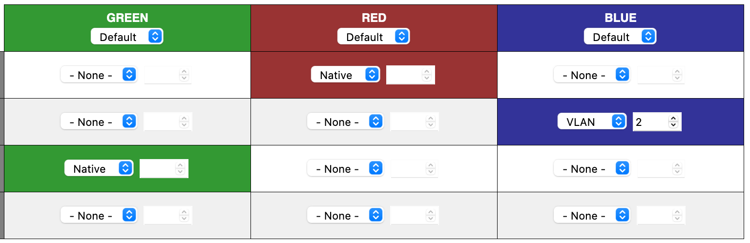
  1. Setup a Vlan on IPFire for BLUE. I used VLAN 112 for that.

Note: When I used the ZOne Configuration, the blue network did NOT come up. I followed the instructions from this video to manually edit the 2 files:

This is my configuration:

/var/ipfire/ethernet/settings

BLUE_ADDRESS=192.168.112.1
BLUE_BROADCAST=192.168.112.255
BLUE_DESCRIPTION=’“pci: Intel Corporation 82572EI Gigabit Ethernet Controller (Copper) (rev 06)”’
BLUE_DEV=blue0
BLUE_DRIVER=e1000e
BLUE_MACADDR=XX:XX:XX:XX:XX:XX
BLUE_MODE=
BLUE_NETADDRESS=192.168.112.0
BLUE_NETMASK=255.255.255.0
BLUE_SLAVES=

/var/ipfire/ethernet/vlans
BLUE_MAC_ADDRESS=XX:XX:XX:XX:XX:XX
BLUE_PARENT_DEV=YY:YY:YY:YY:YY:YY
BLUE_VLAN_ID=112

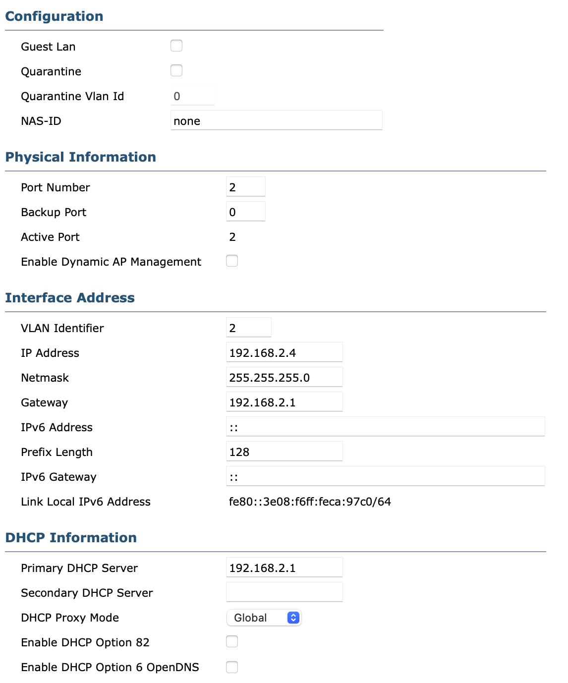
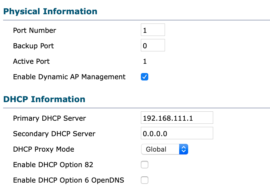
  1. Setup the 5508. By default, it till create an untagged vlan (the management one). – In retrospect, perhaps I should have created the management interface on VLAN 1 –

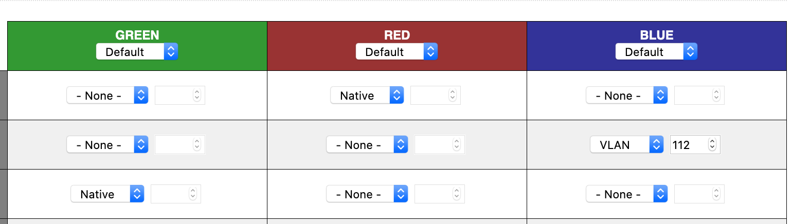
I then created a new interface to handle the blue network. I used VLAN 112, same as the one on IPFire.

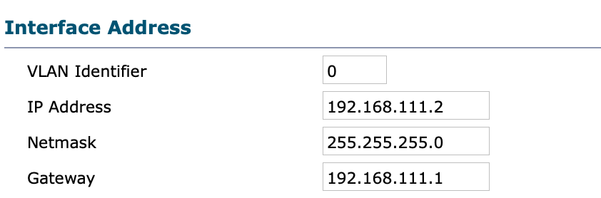
The management Interface looks like this:


While the blue interface looks like this:


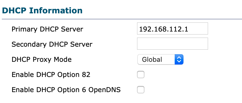
As you can see, both interface use the IPFIre DHCP service and the blue replies on IPFIre MAC filtering to determine who can connect.

  1. Still from the 5508, create 2 WLANs.

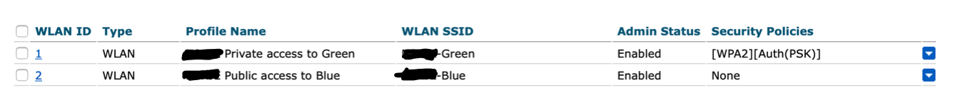
WLAN 1 will be used to add APs to the green network while WLAN 2 will handle blue (hence the names…).

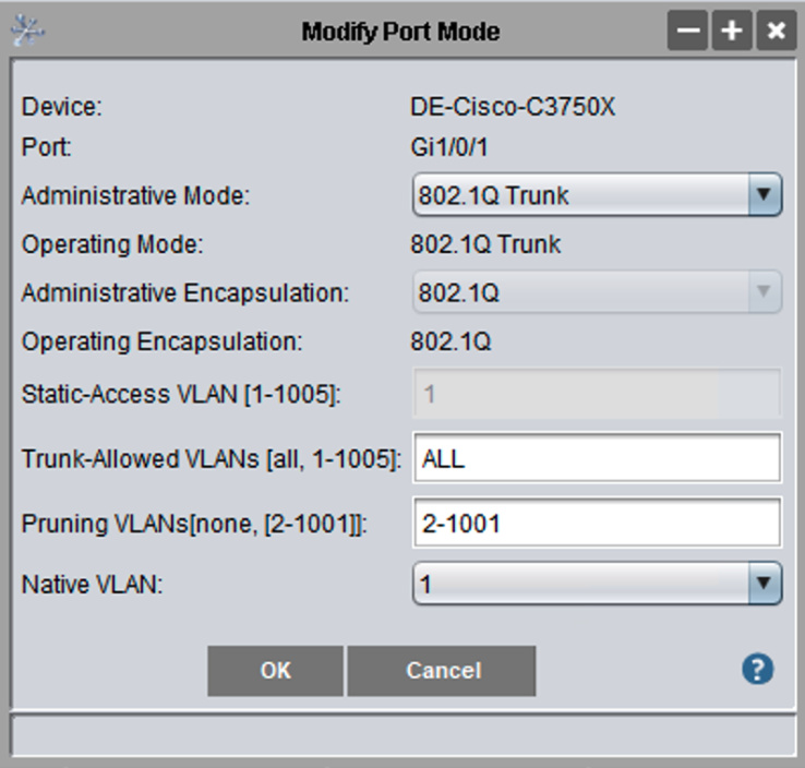
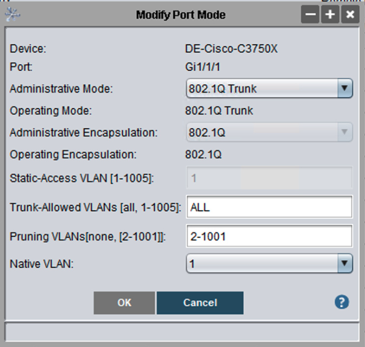
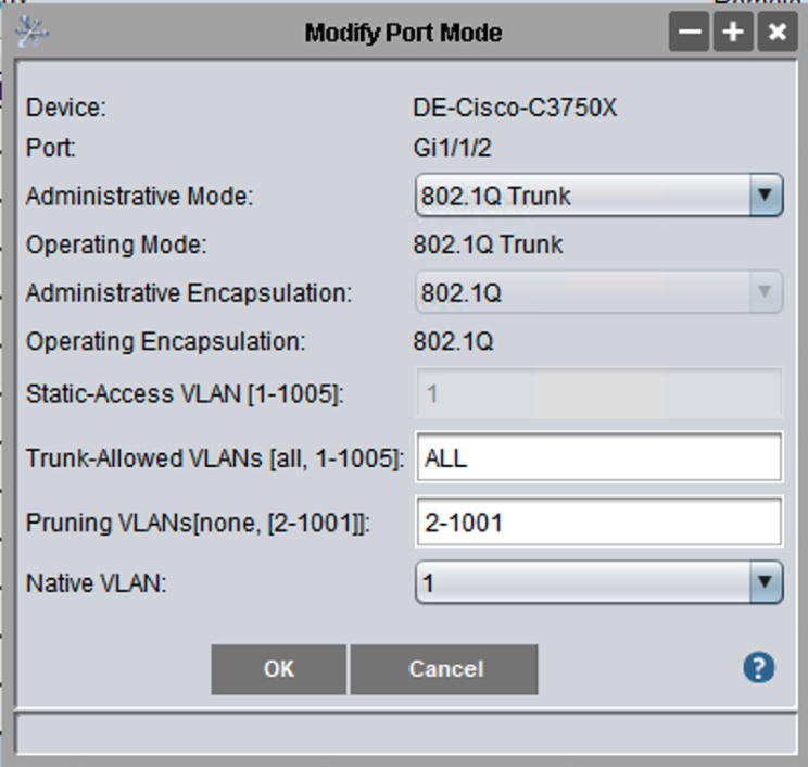
  1. Now go to the 3750X and create 2 “Trunks”, one for connecting the green network to Port 1 of the switch, and one for connecting the 5508 (i.e. management and blue interfaces) to the switch (Ports Gi1/1/1 and Gi1/1/2).


Next I connected everything together:

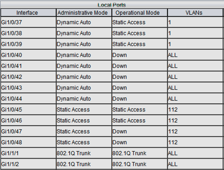
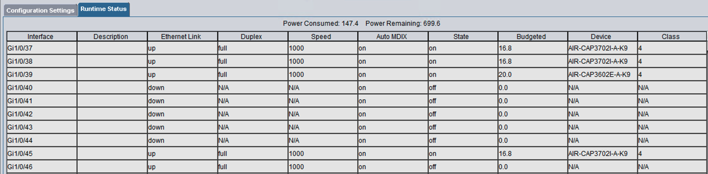
The 3 AP which connect to Green are connected to ports 37, 38 and 39

The AP connect to port 45 of the Cisco switch while the blue network (i.e. VLAN 112) from IPFire connects to port 46 as you can see from here:

.

Next up, I will experiment with LAG on the 5508. I am still not clear on what the benefit specific to my environment would be. Again, I hope that the members more experienced than me could shed some light on this topic and perhaps on the mistakes I made.

I hope this “how to” can be of benefit to other newbie users within the community.

Renato

Hello Renato,

thank you very much for sharing your experience on IPfire with VLAN and a Cisco WLC.

I’m trying to implement a similar setup but having issues with DHCP. What I got working so far:

WLC and AP’s sitting on green as management VLAN (untagged) using IPfires green DHCP server. This is on port 1 of the WLC (2504).
Blue as WLAN 1 on port 2 of the WLC using VLAN 100 and being directly connected to the physical interface for blue having VLAN ID 100 on the IPfire. All devices connecting to WLAN 1 are getting their IP addresses from the blue DHCP server in IPfire.

To implement an additional WLAN for guests I created a second WLAN on port 2 of the WLC having VLAN ID 200 and added a VLAN 200 (via rc.local) to the blue interface on the IPfire. This worked as far as I could ping the VLAN 200 IP address on the WLC from the IPfire but wasn’t able to connect any device to this WLAN 2 even with providing an additional DHCP scope on IPfire via dhcp.conf.local.

Since I didn’t get it working I tried your setup having WLC, AP’s and WLAN1 sitting on the untagged green network on port 1 of the WLC. All devices getting their IP’s from the green DHCP in IPfire.
I changed WLAN2 sitting on port 2 to VLAN 100 directly connected to the blue interface in IPfire but no device can connect because the WLC always using the DHCP on green:

*DHCP Socket Task: Jan 11 00:16:21.768: c6:d8:94:69:98:76 DHCP option: netmask = 255.255.255.0
*DHCP Socket Task: Jan 11 00:16:21.768: c6:d8:94:69:98:76 DHCP option: gateway = 192.168.x.1
*DHCP Socket Task: Jan 11 00:16:21.768: c6:d8:94:69:98:76 DHCP option: DNS server, cnt = 2, first = 192.168.x.1
*DHCP Socket Task: Jan 11 00:16:21.768: c6:d8:94:69:98:76 DHCP option: 15 (len 17) - skipping
*DHCP Socket Task: Jan 11 00:16:21.768: c6:d8:94:69:98:76 DHCP options end, len 72, actual 64

On the WLC I tried all DHCP proxy settings (enabled, disabled, global) but didn’t get it running.

Do you have an idea?

Best, Oliver

P.S. This is the first time ever I’m working with Cisco equipment.
P.S.S. The setup with 2 VLANs on blue is the desired solution but if not possible the second solution is fine as well (management and known devices on green and guests on blue)

Oliver

Sorry for the delay in replying.

You are clearly further along on this than I am. I revisited my configuration with the goal of setting up a “Guest” network which would connect to the Blue network.

These are the steps I followed:

Setup the Blue network to VLAN 2.

Next on the 3750X I issued the following commands:

=====================================================================
--------------   Configuration for the BLUE network    --------------
=====================================================================
# Create a trunk line between the 3750X and the 5508 - Port #2
# This trunk will be used for the Guests network


PA-Cisco-C3750X>en
Password:
PA-Cisco-C3750X#conf t
Enter configuration commands, one per line.  End with CNTL/Z.
PA-Cisco-C3750X(config)#int Gi1/1/4
PA-Cisco-C3750X(config-if)#switchport trunk encapsulation dot1q
PA-Cisco-C3750X(config-if)#switchport mode trunk
PA-Cisco-C3750X(config-if)#switchport trunk allowed vlan 2


=====================================================================
--== Create a trunk on port 47 to connect to the BLUE card of IPFire ==--
=====================================================================
PA-Cisco-C3750X>en
Password:
PA-Cisco-C3750X#conf t
Enter configuration commands, one per line.  End with CNTL/Z.
PA-Cisco-C3750X(config)#int Gi1/0/47
PA-Cisco-C3750X(config-if)#switchport trunk encapsulation dot1q
PA-Cisco-C3750X(config-if)#switchport mode trunk
PA-Cisco-C3750X(config-if)#switchport trunk allowed vlan 2


=====================================================================
--== Create an ACCESS on port 48 to connect the Cisco AP
=====================================================================
PA-Cisco-C3750X#conf t
Enter configuration commands, one per line.  End with CNTL/Z.
PA-Cisco-C3750X(config)#interface Gi1/0/48
PA-Cisco-C3750X(config-if)#switchport mode access
PA-Cisco-C3750X(config-if)#switchport access vlan 2
PA-Cisco-C3750X(config-if)#end

I then created a new WLAN on the 5508.

Connected Port 2 of the 5508 to the Gi1/1/4 port of the switch.

Next, connect the BLUE ethernet card to Gi1/0/47 and the AP to Gi1/0/48.

Lastly, I added the mac address of Port 2 of the 5508 to the list of addresses in IPFire along with the mac address of the AP.

I SSH’ed into the IPFire server and tried to ping the 5508. Nada!!!

[root@ipfirePA ~]# ping 192.168.2.4
PING 192.168.2.4 (192.168.2.4) 56(84) bytes of data.
From 192.168.2.1 icmp_seq=1 Destination Host Unreachable
From 192.168.2.1 icmp_seq=2 Destination Host Unreachable
From 192.168.2.1 icmp_seq=3 Destination Host Unreachable

Any suggestions? In your post you mentioned that you got the blue to work. WHat did you do differently from what I did?