Dual-WAN setting in IPFire (was: Two asymmetric uplinks)

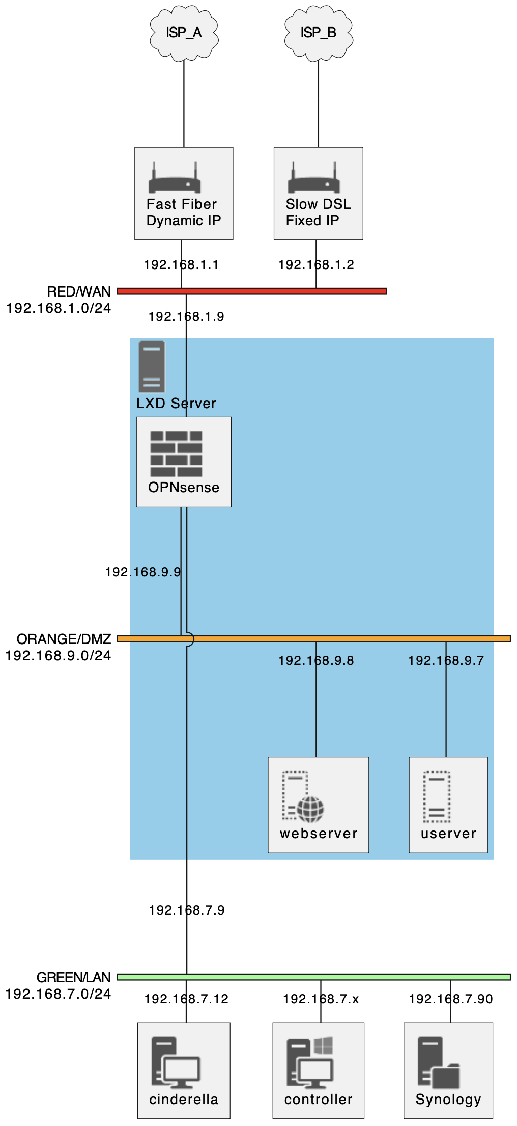
I have the following setup:

  • RED + GREEN + ORANGE
  • Orange has a couple of hosts (mainly used as web server)
  • GREEN has some workstations(~10) and a NAS (doubling as GIT repository)
  • RED has TWO, currently asymmetric) fiber modems:
    • Fast (1000Mb/s) one with dynamic public IP (unreacheable from the Internet)
    • Slow (200Mb/s) one with static public IP (connected to domain I own)

I am currently using “slow” for all my traffic, but I would like to “optimize” a bit.

In general I think I should set up things so that connections originating from GREEN
(and possibly also ORANGE) should go through Fast while connections originating
from the Internet (presumably on Slow, but this may change) should go back using
the “right route” (i.e.: wherever they came from).
Incoming connections can currently go to:

  • a server on ORANGE (80 and 443 at least)
  • NAS on green (accessing GIT through secured SSH connection on non-standard port).
  • I am wondering about moving all reverse proxy/virtual-server handling to IPFire
    (currently all http[s]:// stuff is sent to a single server on ORANGE and handled there).

I am a bit confused about how to setup this beast (and I’m unsure it even makes sense)
as I’m not a real networking expert, even tough I’m meddling with the stuff since a lot
of time.

Cross-check and advice would be very welcome.
Many Thanks in Advance

You want a DUAL-WAN setting. As a Linux distribution this should be possible in IPFire, however it is not supported out of the box and requires a lot of work from your part.

You need to create a second red interface by editing /var/ipfire/ethernet/settings. For example:

CONFIG_TYPE=4
RED_DEV=red0
RED_MACADDR=00:00:00:00:00:00
RED_DESCRIPTION='"pci: Intel Corporation I210 Gigabit Network Connection (rev 03)"'
RED_DRIVER=igb

RED1_DEV=red1
RED1_MACADDR=11:11:11:11:11:11
RED1_DESCRIPTION='"pci: Intel Corporation I210 Gigabit Network Connection (rev 03)"'
RED1_DRIVER=igb

GREEN_DEV=green0
GREEN_MACADDR=22:22:22:22:22:22
GREEN_DESCRIPTION='"pci: Intel Corporation I210 Gigabit Network Connection (rev 03)"'
GREEN_DRIVER=igb

ORANGE_DEV=orange0
ORANGE_MACADDR=33:33:33:33:33:33
ORANGE_DESCRIPTION='"pci: Intel Corporation I210 Gigabit Network Connection (rev 03)"'
ORANGE_DRIVER=igb

BLUE_DEV=blue0
BLUE_MACADDR=44:44:44:44:44:44
BLUE_DESCRIPTION='"pci: Qualcomm Atheros QCA986x/988x 802.11ac Wireless Network Adapter"'
BLUE_DRIVER=ath10k_pci

GREEN_ADDRESS=10.1.1.1
GREEN_NETMASK=255.255.255.0
GREEN_NETADDRESS=10.1.1.0

ORANGE_ADDRESS=10.1.2.1
ORANGE_NETMASK=255.255.255.0
ORANGE_NETADDRESS=10.1.2.0

BLUE_ADDRESS=10.1.3.1
BLUE_NETMASK=255.255.255.0
BLUE_NETADDRESS=10.1.3.0

RED_DHCP_HOSTNAME=ipfire
RED_DHCP_FORCE_MTU=

RED_ADDRESS=0.0.0.0
RED_NETMASK=0.0.0.0
DEFAULT_GATEWAY=0.0.0.0
RED_TYPE=DHCP
RED_NETADDRESS=0.0.0.0

Then the most complex part is to manipulate the routing table, which is done in /etc/sysconfig/rc.local or firewall.local. You would need to add the necessary routing entries to ensure that the correct gateway is used for the correct outgoing interface. This is a complex area and might require a deep understanding of the Linux routing mechanism. Then you might need to create firewall rules to manipulate the traffic for the two different WAN interfaces. Finally, If you want each WAN interface to use a different DNS server, you may need to manipulate the DNS settings.

Keep in mind that unless an IPFire developer steps in to clarify how things really are, this is only a conjecture and it could be completely wrong.

EDIT: I asked GPT4 to show me an example of how the routing manipulation in rc.local would look like. This is the output of the model:

#!/bin/sh
#
# This script will be executed *after* all the other init scripts.
# You can put your own initialization stuff in here.

# Define gateways for red0 and red1 interfaces
GW_RED0="192.0.2.1"
GW_RED1="203.0.113.1"

# Define table IDs
TID_RED0="100"
TID_RED1="101"

# Define marks
MARK_RED0="1"
MARK_RED1="2"

# Flush existing rules
ip route flush table $TID_RED0
ip route flush table $TID_RED1

ip rule del fwmark $MARK_RED0 table $TID_RED0
ip rule del fwmark $MARK_RED1 table $TID_RED1

# Create routing tables for red0 and red1
ip route add default via $GW_RED0 dev red0 table $TID_RED0
ip route add default via $GW_RED1 dev red1 table $TID_RED1

# Add rule to use specific table for marked packets
ip rule add fwmark $MARK_RED0 table $TID_RED0
ip rule add fwmark $MARK_RED1 table $TID_RED1

I personally would not try this in production neither I would rely on a GPT model unless thoroughly tested.

1 Like

Thanks @cfusco.

I’m unsure I understand correctly the first part of your DUAL-WAN setup.
Specifically I don’t really understand the need for double RED.
My setup is (at least currently) to have a single RED (192.168.1.0/24)
with exactly three hosts:

  • Fast modem/router (192.168.1.1)
  • Fast modem/router (192.168.1.2)
  • IPFire (192.168.1.9)

I don’t have a second (actually a fourth) NIC for “RED1”
IPFire box has:

  • RED NIC (192.168.1.9)
  • GREEN NIC (192.168.7.9)
  • ORANGE NIC (192.168.8.9)

I don’t understand why I need a second REED (OTOH need for routing/firewall
rules is clear, even if details are fuzzy in my head).

Could you elaborate, please?

I fully agree on your last comment :wink:

From your description, it seems you’re running a Dual-WAN setup with one RED interface in IPFire, where both WAN connections are within the same subnet. This is a little different from the typical configuration I had in mind, where two separate interfaces would be used.

In your scenario, you can assign a second IP address to your RED interface to create distinct routing paths for your two WAN connections. Here’s how it should be:

First, assign the second IP address to the RED interface:

ip addr add 192.168.1.10/24 dev red0

Next, create separate routing tables:

ip rule add from 192.168.1.9 table 1
ip rule add from 192.168.1.10 table 2

ip route add default via 192.168.1.1 dev red0 table 1
ip route add default via 192.168.1.2 dev red0 table 2

In this example, we have two routing tables: table 1 and table 2. The rules starting with ip rule add specify that if a packet originates from 192.168.1.9, it should use table 1 for routing, and if it originates from 192.168.1.10, it should use table 2. The default routes for each table are added using the ip route add default command.

This way, you can manage traffic from different IP addresses on the same interface independently, which is probably what you want to obtain with the dual-WAN setup like yours.

As a note, I’ve been using the language model ChatGPT-4 to answer to your question (btw, I am curious by nature and problems like this always draw my attention). If you learn how to prompt the AI model, you can also interact directly with the AI to gain further insights. Their answers cannot be taken at face value, but very often they point to the right direction and with the right follow-up you can fill the knowledge gap you need to have the right mental framework. Then, it’s just a matter of testing and refining your questions. If you get the wrong answer, it is because you asked the wrong question.

1 Like

This would be true, if the knowledge base and the processing mechanism are perfect ( and transparent ).
I doubt, latter is true for ChatGPT. :wink:
As hint for the right direction this tool may be efficient. Nevertheless, you have to verify the solution/answer presented.

Generally speaking, I share your doubts, however for this particular topic (IPFIre and system administration in general) I am quite confident that the training data is good and all the answer are present somewhere. It is just a matter of guiding the model to generate the next token following the right path.

absolutely, and usually feeding back the result to the model allows to solve the problem or step closer to solve the problem.

EDIT: to clarify what the model does, you can read this chat that helped me greatly to understand how these generative models work. It is still open, message me if you want to ask something else; I will do it for you and I will update the chat.

That’s interesting and matches completely what I know about SNN (Simulated Neuron Networks) It’s now a couple of decades since I worked in that field, but things did not seem to have radically changed (besides the sheer amount of neurons that’s possible to simulate, of course).

FYI, since ChatGPT did not state it clearly:

  • the “mathematical functions” are actually very simple for each Neuron:
    • there is a large number of digital (0/1) inputs (usually from previous layer, but loops are possible)
    • each input has a weight (one of the “parameters” arranged in “tensors”)
    • at each iteration “active” (1) input weight are summed together and if result is positive output is set to “1”.
  • Network “topology” is simply a description of which Neuron (having a single output) is connected to each input of next layer (thus a “fully connected” means each N, of next layer receives input from ALL N. of previous one.
  • While “working” is local and forward (each N. does not know who is giving inputs and who will use output) training is global and back-propagating:
    • SNN is presented a certain input
    • SNN generates output (based on “previous training”).
    • Output generated is compared with “required response” and a global “correctness” value is computed.
    • Back Propagation starts from output Neurons which modify their weights to match desired output, to minimize weight change (depending on “correctness value” above) N. can request previous layer to rethink its outputs (and thus modify other N. parameters) recursively.
  • usually the same set of data is presented several times until results are “stable” on the whole training set.
  • “curing” of the training set effectively means it can converge to a stable situation where all presented inputs have desired output (“malformed” training sets have an “oscillating behavior” where “fixing” a specific input->output transformation “breaks” other ones)

This is obviously very terse, but I think it can put the above chat in the right perspective.

2 Likes

I am extremely grateful for all the time you spent composing your message to help me out understanding the topic, which is my main intellectual interest these days. You are clearly an expert and I am not even capable of absorbing a fraction of what you wrote. Therefore I asked GPT4 for help. This is what the model replied. I would really appreciate if you could tell me how was the quality of this reply, good, bad, so so?

Regardless whether you decide to answer or not, I appreciate your input.

The original post is providing a rough overview of how artificial neural networks (ANNs) operate, particularly during the training phase. Here’s a simpler explanation of the main points:

Neuron operations: In artificial neural networks, each “neuron” or “node” receives multiple inputs, which are usually outputs from neurons in the previous layer. Each input is multiplied by a “weight” (one of the parameters). If the sum of these weighted inputs is above a certain threshold, the neuron ‘fires’, or sends an output to the next layer. The function determining whether and how a neuron fires based on its inputs is known as the activation function.

Network topology: The network’s structure, or how the neurons are interconnected, is referred to as its topology. In a fully connected network, every neuron in one layer is connected to every neuron in the next layer.

Training the network: The network learns by adjusting its weights based on a process called backpropagation, which is used during training. The network is first ‘fed’ input data and produces an output. This output is compared to the expected output, and the difference (the error) is calculated. This error is then propagated back through the network, and the weights are adjusted in a way that aims to minimize the error.

Training set: The network is usually trained over several iterations (epochs) until the model’s predictions become stable and accurate. The quality of the training data is critical: a well-curated training set will help the model converge to a stable solution where the desired output is obtained for all presented inputs. However, if the training set is not well-formed or balanced, the model may fail to converge and instead keep oscillating, with improvements in one area causing deterioration in others.

The original post appears to be discussing Spiking Neural Networks (SNNs), a type of neural network that more closely mimics biological neurons. These are a bit different from the type of networks typically used in deep learning (like GPT-3), but the core concepts of neurons, network topology, and training are similar across different types of networks.

Note that this is a simplified explanation and many details and nuances have been omitted for the sake of clarity.

ChatGPT rephrasing is absolutely correct (within stated limits of terseness, a full explanation would take MANY more pages, of course).

ChatGPT paragraph 2 is completely equivalent to what I wrote (having a separate “firing threshold” is obviously redundant as scaling all input weight will adjust it to whatever predefined value, including conventional “0”)

Paragraph 3 points out (IMHO in a rather cryptic way) network topology is, in very general terms, a graph where each node receives input either from “outside” or from some previous computational node (i.e.: another neuron); there are two main divisions: cyclic and acyclic graphs.
The cyclic graphs permit feedback loops and resemble more closely actual (biologic) Neural nets.
OTOH acyclic graphs guarantee signal to propagate in “forward” direction with no possible “loop” (this eliminates also chance of an “oscillating” behavior and is generally preferred in nets designed to produce specific output given an input set.
A further restriction often done to graphs is to organize neurons in “layers” where each layer connects only to (possibly all) neurons in the previous layer. This arrangement enables to use well-established linear algebra methods (i.e.: tensor calculus) to compute each layer output. Another side effect is to have two “special” layers: one input layer connected to “starting conditions” (the input token stream) and one output layer providing “results” to outside.

Paragraphs 4 and 5 are essentially a rephrasing of what I tried to put in the bullet points, which is clearer depends solely on reader viewpoint.

Spiking NN are a sub-genere often used together with cyclic topologies: instead of having a “stable output” based on inputs each node receives asynchronous notification events about inputs and, if wights are “right” produces a notification event as output (otherwise it simply remains silent). I didn’t have those in mind as I doubt they are used in massively parallel computations. It is absolutely correct this resembles more closely biological neurons behavior. Each neuron is logically a separate computational unit receiving input through synapses and deciding if and when to “fire” providing input to other neurons connected to its “axon”; this structure is not very well suited to tensor calculus processing.

Note1: I’m not really an expert, even if I brushed the field some time ago; take what I say (from the top of my head) with a generous amount of “salt” :wink:

Note2: Not being a native English speaker (I’m Italian) and given way ChatGPT works (input tokenization and prediction) it is possible (and perhaps even likely) some specific linguistic misalignment could bias system responses in “strange ways”.

1 Like

Sorry for the very late comeback.
Problem is (was) my second ISP failed to deliver the fiber connection till last week, so point in experimenting with two almost-identical uplink was moth (and I had also other problems popping up).

My current setup is like (link deleted - see image below).

My current IPFire setup uses just “ISP B” and the brand new fast fiber is sitting there unused.

Target would be:

  1. Use “ISP A” for all normal traffic (i.e.: traffic originated from GREEN and ORANGE)
  2. Redirect a few ports (essentially 80, 443 and some “non-standard SSH”) from “ISP B” to “webserver” (allowing “webserver” to correctly answer, of course)
  3. If at all possible, to use “ISP B” as fallback if/when “ISP A” goes down.

I am a bit confused by your previous instructions (where to put them and how to convince IPFire to send packets where needed).

As said: currently I can easily use either ISP A or ISP B (simply using setup to change default gateway on RED), but not both.

Any comment welcome :wink:

Mauro


EDIT: Please drag & drop pictures within your post. Sometimes links change or are deleted - moderator

Would you not be able to have a static route to the second gateway?
Have some traffic directed there.
Don’t think it will work as fail over.
But to redirect some types of traffic.

I can surely have a static route, but I fail to understand how it would help me.
Could you elaborate, please?

Unless I’m wrong.
My example would be
ISP 1 main gateway.

ISP 2 static route.
Would think this is possible.

Sorry being real dense.
I don’t understand how a static rout can help me.

I fully agree using ISP_1(192.168.1.1) as my default gateway as it’s fastest outgoing.
That part is clear.

OTOH I fail to understand how I could use a static route to route WEB ports (80 and 443 plus, possibly, some “non standard”) trying to reach ISP_2 (public IP: 79.1.194.217, internal 192.168.1.2) to my nginx reverse proxy (192.168.9.8 on ORANGE) and back.

AFAIK I could use a static route to reach a specific external address (e.g.: www.google.com) using ISP_2 as gateway, but I don’t know how to use it to redirect incoming connections from a random client.

What am I missing?

ISP router 2 would need a port forward rule to direct traffic to ipfire.

Pretty Please,
either take the time needed to write a meaningful answer or avoid replying at all.

OF COURSE I have port forward rules (on both modems, actually).

Problem is not there.

Problem is all response packets are sent to the (unique) “default gateway”, if request came from that all is well, but if it came through the “other one” (whatever it is) reply is sent ALL THE SAME to “default gateway” which didn’t see the request and thus doesn’t know how to how to reverse NAT.

I am unable to understand how to send reply to the same gateway who processed the request, and I’m beginning to suspect it’s not possible, at least with IPFire.

Have a Merry Christmas
and a Very Happy New Year!
Mauro

I happened to come across the topic, and it also interests me. I was under the impression that with IPFire, it was possible to configure only one RED interface, but perhaps I was mistaken, from what I can see. I couldn’t fully understand all the responses in the topic, but I gather that there’s an attempt to use 2 ISPs for some sort of Load Balancing, right?

I’ve managed to do this, but I purchased a TP-LINK multiwan router that I connected in series with IPFire. I would be interested and curious if I could achieve the same by eliminating the multiwan router. I had pondered this issue in the past and opened this topic:

Merry Christmas!!!

1 Like

From what I gathered it is actually not possible to have a true multi-wan in IPFire (updates to this welcome, of course).

It seems to be possible to setup a multi-wan/multi-gateway by issuing low level commands to underlying Linux, but IMHO that would forfeit all “value added” given by a router distribution like IPFire (essentially: security is gone, you are on your own).

I am approaching problem from a completely different angle: I am experimenting with OPNsense which explicitly support multiple gateways.

Please correct me if I’m wrong.

Merry Christmas
Mauro

1 Like

My understanding is that multi-wan is not possible on IPFire-2.x without significant reworking of the code. The devs will not look at doing that, as that would divert them from working on IPFire-3.x and supporting IPFire-2.x from security issues and bugs to existing capabilities.

From my understanding IPFire-3.x should be able to do what you want as it is being designed to be able to have as many interfaces and zones as you want to have and to use them in whatever ways you want, such as vlans, bridging, bonding etc.

2 Likes

Thanks for the news!
Is there any rough estimate about when IPFire3 will be available for beta?
The only available preview is quite old.
Is the project actually alive?

Thanks in Advance and
Merry Christmas!

Mauro

1 Like